|
|
|
One of the common modifications that many other Ford Powerstroke Diesel owners have done is to upgrade the small Motorcraft GPR to the
White-Rogers (Stancor) 586-902 relay, a real monster compaired to the original GPR.
Every year, hundreds of Powerstroke owners experience Glow Plug Relay failures, usually about the time when the coldest
Artic front of the season makes its way down from Alaska......That's what happened to me quite a few years ago and the thought of changing
out the GPR when the outside temperature was -16 F was less than exciting so I decided to try the White-Rodgers unit.
The White-Rodgers Stancor Contactor (I'll call it a White-Rodgers GPR from now on) can now found at
DieselOrings.com
NOTE: If you have a Late 99-03 California emissions truck or Excursion, you will most likely have a Glow Plug Control Module
under your hood, not a GPR.
Check before ordering one because this mod will not work for you.
Got a question? Contact me on my DieselOrings.com webshop CONTACT PAGE
|
[Click on a thumbnail to see a larger image - -
javascript must be enabled and popups allowed from this site]
|
|
Testing your old Glow Plug Relay
- Measure the voltage between chassis ground and the battery + terminal then again
between both terminals. If there is any difference at all, you have a battery ground problem.
- If not, then measure between ground and the "always hot" large terminal post on
the GPR, this reading should be the same as what you measured on the battery.
You will need help for the next steps or at least have a good view of the meter form the driver seat.
- Have someone turn on the key and measure the voltage on the large "always hot" post
again between chassis ground and this post. It should drop from what you measured with the key off.
Write down this measurement.
- Quickly (before the PCM tries to turn off the GPR), measure the voltage on the post opposite the "always hot"
large terminal between chassis ground and this post. This is the post that feeds the glow plugs. If
your voltage measurement there is less than .2 volt lower than the "always hot" post, the relay
is beginning to have the contacts burned from arcing. Otherwise it is working fine and you may have
a glow plug problem.
- If you have no voltage on the large post when you turned the key on, you need to check to
see if the GPR is getting activation voltage.
- With the key on, test voltage between chassis ground and the red wire on the small post.
You should have battery voltage there, if not, your GPR coil is not getting 12volts and
there is an electrical problem in the wiring.
- If there is voltage there, take a small length of #16 wire and ground the opposite (from the small red wire)
small post to chassis ground while reading the voltage on the large post feeding the glow plugs.
This small wire should be an orange color. When you ground this post to chassis, the relay
should energize and you will see close to battery voltage on the post feeding the glow plugs.
- If you get no battery voltage reading, the coil may be bad in the relay. If you do get a voltage reading,
you could have a number of bad glow plugs and you will have to ohm them out to see which ones are bad.
|
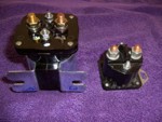 |
Parts used for this serviceWhite-Rogers (Stancor) 586-902 relay.
Here is the White-Rodgers GPR compared
to the NAPA GPR-109 relay. I couldn't belive the difference in size and weight when I looked at the two of them, side by side.
The contact rating on the new relay is 200 Amp continuous and 600 Amp inrush with a 21 ohm coil
resistance. Now this relay looks and feels like its ready to do some serious work.
|
|
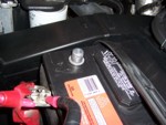 |
Disconnect batteriesDisconnect both positive battery connectors. The cable to the GPR that is booted is always
hot so to keep from accidentally shorting the batteries to ground, the batteries must be disconnected during this service.
|
|
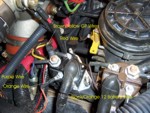 |
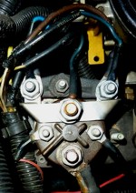
Remove the old GPR
The old GPR has 2 small terminals and 2 large terminals. The small terminals are the electromagnetic coil actuator. There is no
polarity to these terminals and the small red wire and orange wire are connected to the smaller terminals.
The two large terminals are the
contacts to energize the glow plugs. These terminals also do not have polarity but notice that the purple wire (blue) is connected to the
same terminal that the Yellow and Brown glow plug wires are connected to.
|
|
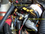 |
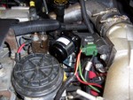
Install the new White-Rodgers GPR
Here is the new White-Rodgers GPR mounted on the original GPR mounting posts. The White-Rodgers unit's mounting bracket fit the
posts perfectly when positioned at a 45* angle to the engine. The only tight spot was trying to mount the relay on the posts. I
found by starting the nut on the post closest to the fuel bowl, then slipping the White-Rodgers' bracket under the nut it was easy to
drop the other side of the bracket over the rear post and tighten both nuts.
Note how the colored wires have been positioned on the various posts.
Orange and Red wires to the small terminals, Purple and the Yellow and Brown GP wires to one large terminal and the battery
feed to the other large terminal.
|
|
 |
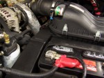
This is a picture of how the White-Rodgers GPR looks when viewing from the driver's side of the engine compartment. Plenty of
room around the GPR and the wire routing to the terminals was easier than on the 109 that had to be turned 90* to fit the
factory bolts.
|
|
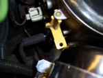 |
During the installation, I was concerned that the larger White-Rodgers GPR may interfere with the operation of the fuel filter bowl
drain valve. I was relieved to find that there was more than enough room to reach down and operate the yellow drain valve with the
new GPR in place.
|
|
 |
Reconnect the batteries
Reconnect both of the batteries positive cables. You can test the action of the GPR by using a DVM to measure 12vdc on the
large terminal that the Yellow and Brown wire is connected to. Test between this terminal and ground for 12 volts when the ignition
key is turned to the run position. The meter should display around 12.5 volts for up to 2 minutes depending on engine and ambient
air temperature.
|
|
 |
NOTE FOR TRUCKS WITH A GPR SHUNT:
It is possible to replace the factory GPR on trucks with the shunt on the outlet power terminal. It will be necessary to bend the outer terminals
of the shunt to fit the larger White-Rodgers relay but it will not damage the shunt to do this.
WIRING:
If you remove the wiring on the shunt, make sure that you wire the shunt back up properly.
There are three smaller blue wires going to the shunt. One of the blue wires is connected to a fusable link and then to a white/green trace wire.
This wire must be connected to
the large center post (relay outlet) where the shunt connects to the GPR.
The larger brown GP wire and the blue wire that is connected to a fusable liknk and then to a white/purple trace is connected to one side of the shunt.
The remaining blue wire and Yellow GP
wire is connected to the other side of the shunt. It does not matter which side is connected to the shunt as long as you match the correct blue wire
with the GP wire.
|
Back to guzzle's Powerstroke Modification Index |


)
)
)
)
)
)
)